Mission Briefing
By the end of this mission, you will be able to:
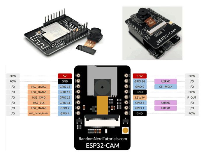
Identify the ESP32-CAM's key pins and explain why it needs an FTDI programmer
Install ESP32 board support in the Arduino IDE
Upload the built-in CameraWebServer example sketch
Find the camera's IP address using the Serial Monitor
Let's Get Started
Every robot you've built so far has moved, sensed, or lit up — but none of them could actually SEE. That changes today. The ESP32-CAM packs a real camera onto a tiny microcontroller board, letting your projects take pictures, stream live video, and eventually even recognize what they're looking at.
There's one quirk to know up front: the ESP32-CAM has no built-in USB port. To upload code, you need a separate FTDI programmer — a small USB-to-serial adapter that acts as a temporary bridge between your computer and the board.
Robo says: "I've had motors, sensors, and lights before, but never eyes! Today I finally get to see the world I'm operating in."
Why You Need An Ftdi Programmer
Most ESP32 boards have a USB chip built right in, so you can plug in a USB cable and upload code directly. The ESP32-CAM skips that chip to save space and keep the board small and cheap — which means you need an external FTDI programmer wired to a handful of pins to upload your sketches.
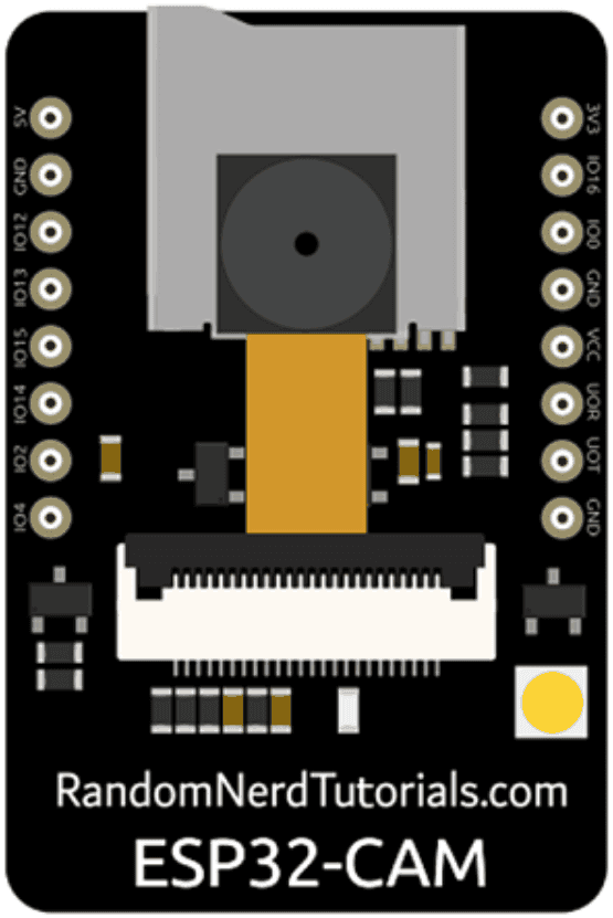
U0R (RX) and U0T (TX) — the serial pins used to send code to the board
5V and GND — power the board during programming
IO0 — must be connected to GND only while uploading ("flashing"); this puts the board into programming mode
After a successful upload, you disconnect IO0 from GND and reset the board so it boots normally instead of waiting for new code.
Your First Look: Camerawebserver
The Arduino IDE ships with a ready-made example called CameraWebServer. It configures the camera, connects to your WiFi network, and hosts a simple web page showing a live feed — all without you writing a single line of camera code yourself. It's the perfect way to confirm your hardware works before you start customizing anything.
Equipment
- ESP32-CAM module
- FTDI programmer
- USB cable
- Breadboard & jumper wires
Circuit Diagram
ESP32 board reference
Activity
Install ESP32 board support in the Arduino IDE, open the built-in CameraWebServer example sketch, wire the ESP32-CAM to the FTDI programmer, and upload the sketch.
Code
// Simplified structure of the CameraWebServer example
#include "esp_camera.h"
#include <WiFi.h>
const char* ssid = "YOUR_WIFI_NAME";
const char* password = "YOUR_WIFI_PASSWORD";
void setup() {
Serial.begin(115200);
WiFi.begin(ssid, password);
while (WiFi.status() != WL_CONNECTED) {
delay(500);
Serial.print(".");
}
Serial.println("");
Serial.print("Camera ready! Open this IP in your browser: ");
Serial.println(WiFi.localIP());
// startCameraServer() is provided by the example sketch
startCameraServer();
}
void loop() {
delay(10000);
}
Did You Know?
- • The IO0 pin trick you used today — grounding a pin to enter programming mode — is the same basic technique used on almost every ESP32 and ESP8266 board that lacks a built-in USB chip. Once you know it, you can flash all kinds of budget boards!
🔧 Try It Yourself
After uploading, open the Serial Monitor, find the printed IP address, and type it into a web browser on the same WiFi network. Describe what you see on the page.
• IP address I found:
• What loaded in my browser:
// Simplified structure of the CameraWebServer example
#include "esp_camera.h"
#include <WiFi.h>
const char* ssid = "YOUR_WIFI_NAME";
const char* password = "YOUR_WIFI_PASSWORD";
void setup() {
Serial.begin(115200);
WiFi.begin(ssid, password);
while (WiFi.status() != WL_CONNECTED) {
delay(500);
Serial.print(".");
}
Serial.println("");
Serial.print("Camera ready! Open this IP in your browser: ");
Serial.println(WiFi.localIP());
// startCameraServer() is provided by the example sketch
startCameraServer();
}
void loop() {
delay(10000);
}
Think About It
🤔 Discuss With a Partner or Write Your Answer
Why do you think the ESP32-CAM's designers chose to leave out a USB chip, even though it makes programming slightly more inconvenient?
Quick Recap: Fill In The Blanks
1. The ESP32-CAM requires an external __________ programmer because it has no built-in USB chip.
2. The __________ pin must be connected to GND only while uploading new code.
3. U0R and U0T are the board's __________ pins, used to transfer code from your computer.
4. The built-in example sketch that hosts a live camera feed is called __________.
Match It!
Draw a line (or write the matching letter in the blank) to connect each word to its meaning.
Check Your Understanding
I can identify the ESP32-CAM's key pins and explain why it needs an FTDI programmer
I can install ESP32 board support in the Arduino IDE
I can upload the built-in CameraWebServer example sketch
I can find the camera's IP address using the Serial Monitor
Quiz Time!
Question 1: Why does the ESP32-CAM need an FTDI programmer?
🔍 Reveal answer (drag-select the blank space):
Question 2: What must IO0 be connected to during upload?
🔍 Reveal answer (drag-select the blank space):
Question 3: Where do you find the camera's IP address after a successful upload?
🔍 Reveal answer (drag-select the blank space):
Challenge Zone
🏆 Level Up
Research (or ask your instructor) what happens if you forget to disconnect IO0 from GND after uploading and then try to reset the board. Write down your prediction, then test it if you're able to safely do so.
Robot Journal
Think about the first time you saw a live video feed appear from a board you programmed yourself. What was that moment like, and what do you want to try pointing the camera at first?
Lesson Wrap-up
🤖 Robo Says
Robo says: "I can finally see! Next, let's teach me to remember what I see by saving photos."