Mission Briefing
By the end of this mission, you will be able to:
Explain what a motor driver does and why a microcontroller can't power a motor directly
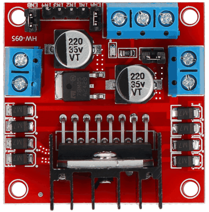
Identify the ENA, IN1, and IN2 pins on an L298N/L293D motor driver
Wire an ESP32, a motor driver, and an external power supply to a DC motor
Write code that turns a DC motor ON and OFF using digitalWrite()
Let's Get Started
Every robot needs muscles — and for wheels, propellers, and conveyor belts, that muscle is the humble DC motor. But there's a catch: a DC motor is a power-hungry beast, and your ESP32's pins are not built to feed it directly.
Today you're introducing a new teammate: the motor driver. Think of it as a bodyguard and translator rolled into one — it takes the ESP32's tiny, safe signals and turns them into the strong electrical push a motor needs, without ever letting the motor's hunger for current fry your microcontroller.
Robo says: "Motors are strong, but they're clumsy with electricity! Never let ESP32 touch a motor directly — always introduce them through a motor driver first!"
Why You Can't Just Plug In A Motor
An ESP32 pin can safely supply only a few dozen milliamps of current. A small DC motor, especially at startup, can pull hundreds of milliamps or even amps — way more than the ESP32 can provide, and way more than its pins can survive.
A motor driver module (like the L298N or L293D) solves this with an H-Bridge — a clever arrangement of four electronic switches that lets a small control signal from the ESP32 direct a much larger current from a separate power supply into the motor. The ESP32 stays safe; the motor gets the power it needs.
Meet The Motor Driver Pins
On most L298N-style drivers, three pins matter most for basic control:
IN1 and IN2 — control signals from the ESP32 that decide which way current flows through the motor
ENA (Enable A) — must be HIGH (or receiving a PWM signal) for the motor to receive any power at all; think of it as the driver's master power switch for that motor
Separate motor power terminals — connect to an external battery or power supply (5–12V), NOT to the ESP32's own power pins
Notice that the motor's power comes from its own supply, while the ESP32 only sends the low-power control signals. This separation is what protects your microcontroller.
Equipment
- ESP32 development board
- DC motor
- Motor driver module (L298N or L293D)
- External power supply, 5–12V (battery pack or bench supply)
- Jumper wires
- Breadboard (optional)
Circuit Diagram
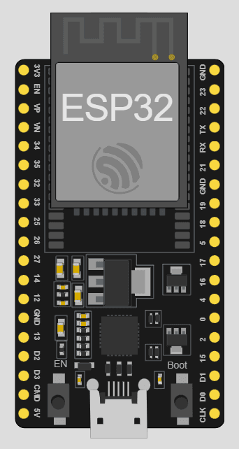
ESP32 board reference
Activity
Wire up the motor driver and write a program that turns the motor ON for 2 seconds, then OFF for 2 seconds, on repeat — like a robot heartbeat.
Code
int motorPin1 = 14;
int motorPin2 = 12;
void setup() {
pinMode(motorPin1, OUTPUT);
pinMode(motorPin2, OUTPUT);
}
void loop() {
// Motor ON (forward)
digitalWrite(motorPin1, HIGH);
digitalWrite(motorPin2, LOW);
delay(2000);
// Motor OFF (stop)
digitalWrite(motorPin1, LOW);
digitalWrite(motorPin2, LOW);
delay(2000);
}
Did You Know?
- • The "H" in H-Bridge comes from the shape the four switches make when drawn in a circuit diagram — it literally looks like the letter H, with the motor sitting across the middle bar!
🔧 Try It Yourself
Change the delay values so the motor stays ON for 5 seconds and OFF for 1 second. Then try making it blink ON/OFF quickly (200ms each) — what happens to the motor's sound?
• My ON delay:
• My OFF delay:
• What I noticed about the fast blinking:
int motorPin1 = 14;
int motorPin2 = 12;
void setup() {
pinMode(motorPin1, OUTPUT);
pinMode(motorPin2, OUTPUT);
}
void loop() {
// Motor ON (forward)
digitalWrite(motorPin1, HIGH);
digitalWrite(motorPin2, LOW);
delay(2000);
// Motor OFF (stop)
digitalWrite(motorPin1, LOW);
digitalWrite(motorPin2, LOW);
delay(2000);
}
Think About It
🤔 Discuss With a Partner or Write Your Answer
Why do you think the motor driver needs its OWN power supply instead of just borrowing power from the ESP32's 5V or 3.3V pin?
Quick Recap: Fill In The Blanks
1. A motor driver protects the ESP32 by handling the motor's high __________ demand.
2. The clever four-switch circuit inside a motor driver is called an __________.
3. The ENA pin must be __________ for the motor to receive power.
4. Motor power comes from a __________ power supply, not from the ESP32.
Match It!
Draw a line (or write the matching letter in the blank) to connect each word to its meaning.
Check Your Understanding
I can explain what a motor driver does and why a microcontroller can't power a motor directly
I can identify the ENA, IN1, and IN2 pins on an L298N/L293D motor driver
I can wire an ESP32, a motor driver, and an external power supply to a DC motor
I can write code that turns a DC motor ON and OFF using digitalWrite()
Quiz Time!
Question 1: Why can't a DC motor connect directly to an ESP32 pin?
🔍 Reveal answer (drag-select the blank space):
Question 2: What does the ENA pin control?
🔍 Reveal answer (drag-select the blank space):
Question 3: Where should the motor's power come from?
🔍 Reveal answer (drag-select the blank space):
Challenge Zone
🏆 Level Up
Add a third state to your code: a "slow blink" pattern where the motor pulses ON for 500ms, OFF for 500ms, five times in a row, then stays OFF for 3 seconds before repeating.
Robot Journal
If you were designing a robot that needed to lift something heavy, why would understanding the motor driver's job matter to you as an engineer?
Lesson Wrap-up
🤖 Robo Says
Robo says: "You just gave your robot its first working muscle! Next up: teaching that muscle which direction to move."